SHADE1
Optical micrometer for online diameter measurement.
MEASURING PRINCIPLE
The laser beam for the Shade1 laser micrometers is output from the optical transmitter as a parallel aimed laser beam. The laser line strikes a CCD array in the receiving optical system. The amount of light collected by this receiver is read out and stored as a digital value in a data field.
If there is a object in the laser-line, only the receiving elements of the lines outside the
shadow zone of the measurement object are illuminated. As the spacing of the pixels of the CCD array is known, the size and position of the measurement object can be determined.
SHADE1 GALERIE
DOWNLOAD INTERACTIVE 3D-CONSTRUCTION HERE
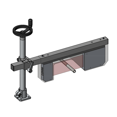
SYSTEM DESIGN
Shade1 consists of a light source and a receiving unit.
The complete controller electronics are integrated in the housing.
Shade1 can be used in both the vertical as well as the horizontal positions
CONTROLLER FEATURES
ANALOGUE
SERIAL
LASER
Semiconductor laser, 670nm, DC-operation, ≤0,39mW max opt. power, laser class 1, the use of these laser sensors therefore requires no additional protective measures Permissible external light ≤5000Lux 2) Optical filter interference filter, red light filter RG630, polarization filter Housing material aluminium.
CONNECTION TO PC
Optional USB connection - with Windows Software for Calibration and set point value teaching.
LED-INDICATION
LED red (+): measured value > upper tolerance threshold
LED green: measured value lies within tolerance window
LED red (-): measured value < lower tolerance threshold
LED yellow: multifunction
EMC IEC 60947-5-2
Shock 15g / 6ms
Vibration 15g / 10Hz…1kHz
Protection class electronics IP 54, optics: IP 67
Operation temperature -10°C to +50°C
Storage temperature -20°C to +85°C
OUTPUT
Analogue: 0 …+10V (scalable)
Digital: (OUT0, OUT1, OUT2): pnp bright-switching/npn dark-switching or pnp dark-switching/npn bright-switching, adjustable using Windows, 100mA, short-circuit proof
DIGITAL INPUT
IN0 external trigger, input voltage +Ub/0V with protective circuit
IN1 teach/reset, input voltage +Ub/0V with protective circuit
Power supply +15VDC …+ 30VDC
Sensitivity adjustment using Windows via PC (parameterization software included)
Laser adjustment adjustable using Windows via PC
Consumption typ. 200mA
The quoted technical data apply for a displacement transmitter to receiver about 800mm and a temperature of 20°C.
Display resolution of the software ≥10μm
Shadowing from ambient daylight increases the signal stability.
The controller is equipped with a display offering multicolour backlighting which changes its colour in the case of exceeding the limit value while a signal is displayed. All user selectable functions of the controller and the measured values can be viewed, displayed and stored in real time via your own web browser without additional Software.
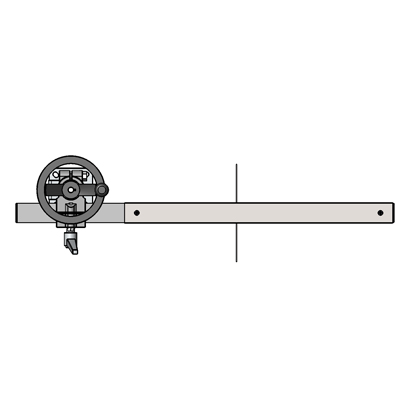
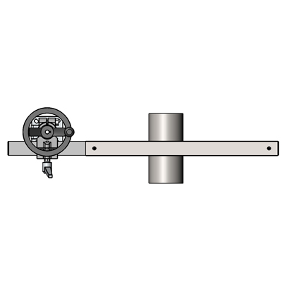
EXAMPLE
Measurement of diameters with two Shade1 Units.
The diameter to be measured can be increased up to 550mm using the Shade2 Unit.
Laser class 1: IEC 60825-1: 2008-05
The Shade1 uses a semiconductor class 1 laser with a wavelength of 670nm. The maximum optical output power is ≤0.39 mW.
This laser class does not require any additional protection equipment.
IMPRINT · DISCLAIMER
2014 TECVANTAGE · ALL RIGHTS RESERVED
 |
+49 179 6700 767 |  |
info@tec-vantage.com |
|---|